A breadboard is a plastic board with holes in it that we can push wires and component legs into in order to connect them together and build a circuit without using a soldering iron. This makes breadboards very hand when we are prototyping and trying out ideas or just mucking about and experimenting. We can easily pull cables and components back out of the holes and reconfigure our circuit as we please.
The images above show how the holes are connected together under the surface of the breadboard. The yellow lines show holes connected together, and the red and black lines show holes that are connected together and usually used for power / positive voltage (red) and ground / zero voltage (black).
As a quick intro to using the breadboard and here is a quick project simply powering an LED with a 9V battery. (warning, photos from the olden days)
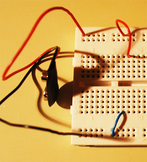
First connect the red and black leads of the battery clip to the power and ground “rails” of the breadboard:
Then, using two jumper cables we can connect the power rails to to rows on the middle of the breadboard.
Now lets connect one leg of our current limiting resistor to one of the other holes on the same row as we connected our power rail. Look at the pictures at the top of the page showing how the holes are connected inside the breadboard f you are confused.
Now its time to connect the LED. If you have allready read the section on LEDs then you might remember that its important to connect it the right way around. The current wants to flow from the long leg to the short leg- So we connect the long leg to the other end of our current limiting resistor, and the short leg to one of the holes in the same row as we connected ground earlier.
Now once we connect our 9V battery to the battery clip, the LED should light up.
If not, check all the connectrions again before you start crying.
PS, if we for some weird reason hate breadboards, we can make the same circuit with crocodile clips: